1
Preface
1.1
Introduction
Think about
radio, and what often comes to mind is the crystal clear music and spoken words
broadcast by FM stations. But radio wasn't always so advanced or so popular.
Like many technologies, it evolved gradually and gained acceptance slowly.
It all
started when Guglielmo Marconi, an Italian inventor, brought electromagnetic
waves out of the laboratory and into the world. He began with short-distance
broadcasts in his own back yard. In September 1899, he astounded the world by
telegraphing the results of the
A steady
stream of inventions pushed radio forward. In 1907, American inventor Lee De
Entertainment
broadcasting began in about 1910. The period between the late 1920s and the
early 1950s is considered the Golden Age of Radio, in which comedies, dramas,
variety shows, game shows, and popular music shows drew millions of listeners.
But in the 1950s, with the introduction of television, the Golden Age faded. Still,
radio remained a pop-culture force. Developments like stereophonic
broadcasting, which began in the 1960s, helped radio maintain its popularity.
Even today,
radio continues to evolve as it competes with other technologies to attract and
hold an audience. Among contemporary developments in radio is Digital Audio
Broadcasting, or DAB. In 1981 the IRT (Institut für Rundfunktechnik) started
the development on DAB, but it had not received ITU approval until 1994.
According to proponents, DAB provides compact disc-quality sound without
interference at any distance. DAB listeners can also become watchers:
information such as programming schedules, and traffic and weather information
can be digitally displayed on stereo "monitors" or LCD screens.
Already
more than 100 years old, radio is still a used media in daily life. According
to a 1998 Arbitron report, over 95 percent of Americans listen to radio at
least once a week. And with new technologies like DAB, the humble radio wave
will likely retain its power for some time to come.
1.2
History
of DAB
1981: The development of DAB was started by the
“Institut für Rundfunktechnik” (IRT).
1987: DAB became part of the European Research
project under the name
1987: The Fraunhofer Institut in
1990: Foundation of “DAB Plattform” in
1994: For better coordination of the development of DAB
in
1995: In July the European Conference of Postal and
Telecommunications Administrations (CEPT) met in
DAB System was
standardised in EN 300 401 by ETSI (European Telecommunication Standards
Institute)
Later on the ITU
recommended Digital System A (
1997: The first personal receivers have been
presented at the IFA97 in
Start of transmission
in
1998: For the EXPO98 in Lisbon RDP started to transmit
DAB over one frequency band
DAB Transmission
started in a lot of European Countries,
2000: In January the Eureka 147 Consortium ended its
work on the DAB system and merged into the World DAB forum.
2003: In September the DAB and DRM Consortium (see 5.1) agreed to collaborate on the development of their systems and to foster conditions that are
favourable for both digital systems’.
2004: By
April over 500,000 receiver had been sold in the
30th of November the DAB
network in
1.3
Why
do we need DAB?
Advantages
of digital microwave links are as follows:
-
Digital
transmission is more “robust”, error free and predictable under most conditions
-
Digital
transmission makes more efficient use of spectrum and have better threshold
margins
-
Digital
transmission has a more rectangular spectrum mask/better adjacent channel
rejection
-
no
quality loss through transmission
-
designed
for mobile reception
-
multimedia
application
-
more
efficient use of the frequency bands (SFN)
-
no
negative interference
-
on
every FM Channel it can be send up to 6 DAB radio channels and data
-
consumes
less energy; better for environment
2
COFDM
– Modulation in DAB
The signal
that is sent over the ether in Digital Audio Broadcast is modulated using
COFDM. The acronym stands for Coded Orthogonal Frequency Division Multiplexing.
The OFDM part reflects that the modulation technique modulates the signal on a
number of frequencies which are all orthogonal to each other. That they are
mutually orthogonal means that the different frequencies will not affect each
other. The Coding refers to a forward correction coding which is added to the
signal to increase its robustness. Both COFDM and OFDM devices will be
mentioned in this text.
2.1
The
transmitter
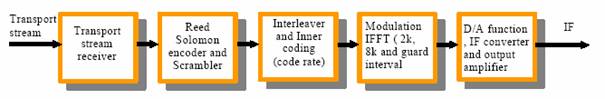
Figure 2.1 A Simplified block diagram of a
COFDM modulator
The audio
signal is first digitalized and compressed, by psychoacoustic encoding, using
MPEG-1-Audio Layer-2 [ 1]. This happens before the signal enters the blocks in
Figure 2.1.
To the
resulting MPEG encoded data stream is then added a forward error correction
encoding to enable the receiver to detect and correct byte errors. Different
forward error correction encoding schemes are used in COFDM, but Reed-Solomon
or CRC (Cyclic Redundancy Check) are the most common. Reed-Solomon encoding
adds 16 parity bytes to the MPEG-2 packet size of 188 bytes, giving a total
packet size of 204 bytes. This enables the receiver to detect and correct up to
8 byte errors per MPEG packet.
This error
corrected stream is then rearranged in a new order (interleaved) to minimize
the effect of burst noise interference. If interleaving is not used, the chance
of consecutive bytes received in error increases. This in turn would make it
harder to error correct the data on the receiver side. The interleaving
combines 12 bytes from different MPEG-2 packets. This makes it possible that up
to 96 bytes can be received in error before Reed-Solomon is unable to correct
it. Interleaving is not obligatory in OFDM. It is not used in COFDM for DVB
because of the higher bandwidth of the signal. Interleaving would introduce too
much delay on the signal. Another reason stems from the fact that the video
transfer standard DVB is not specifically designed for mobile receivers.
Because of the stationary receivers, the reception does not experience the same
problems as DAB, so the interleaving is not necessary.
After the
Reed-Solomon encoding, convolutional coding is added, which multiplies the
signal with a pseudorandom sequence running faster than the data. This adds
bits to the data stream for error protection. This convolutional coding is
using an algorithm called Viterbi algorithm. A figure showing the building
blocks of the encoder is given below.
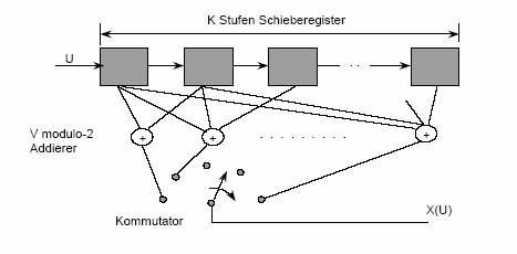
Figure 2.2 Viterbi convolutional encoder
The input
to the encoder is the
time interleaved forward error corrected bit stream, and the output is a
convolution of the input with a pseudo random code.
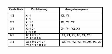
Figure 2.3 Output of the convolutional encoder
Example output sequences are shown in Figure 2.3. The convolution adds redundancy to the signal,
thereby making it more error resistant.
One of the
main features of COFDM is that the signal is split and transmitted over several
different carrier frequencies. Two and two bits of the interleaved and inner
coded stream are mapped to one of four quaternary phase shift keying (QPSK)
symbols. Transmission mode 1, which is one of the standards of OFDM
transmission, uses 1536 pairs of bits. This gives one symbol per carrier
frequency. There are several transmission standards for OFDM transmission with
different number of carriers and different modulation techniques. These
modulation techniques include 64QAM and 16QAM which have a higher bit/symbol
rate. The higher bit/symbol rate is necessary in digital video transfer because
video contains more information than audio. The drawback is that the higher
bit/symbol rate increases the risk of bit errors due to phase noise or variable
attenuation.
Figure 2.4 QPSK constellation diagramme
Figure 2.5 16QAM and 64QAM constellation diagrams
A simple
visualisation of the different modulation techniques is shown in Figure 2.4 and Figure
2.5. The dots or crosses represent the amplitude and
phase of the signal after modulation. The Re/Im and Q/I labels on the axes
refer to the imaginary and real part of the signal in Cartesian coordinates.
The amplitude is the absolute value of the signal. Figure 2.4 shows the QPSK constellation diagram. The only
variable in QPSK is the phase, the amplitude doesn’t change. One important
thing shown in the diagram is that the distance between the symbols decreases
as the number of symbols increases. This makes the system more susceptible to
noise. If the sent symbol is influenced by noise, either phase noise or
amplitude noise, it might be detected as a neighbouring symbol. This introduces
error to the bit stream which has to be corrected by error correcting codes.
Digital Radio Mondial (DRM), the new digital AM equivalent uses 16QAM and
64QAM. DRM is has got less physical bandwidth (9 KHz) because it follows the
analogue AM standard. Therefore it has to have higher symbol density to be able
to transmit enough data.
The
subcarriers in OFDM are all orthogonal to each other, which implies that where
one carrier has a peak, all the other carriers are zero. There is a spacing of
1 kHz between every carrier frequency to minimize the chance of neighbouring
carriers interfering with each other. Adjacent bytes are transmitted in non
adjacent frequency carriers to counter the effect of frequency selective
fading. The modulation of the signal onto the different carriers is done by
inverse fast Fourier transformation (IFFT).
Figure 2.6 A block diagram of a COFDM transmitter
Figure 2.6 and Figure
2.7 show the parts of the COFDM transmitter. Figure 2.6 gives a more complete picture of the total modulator,
as it includes the forward error correction encoder and interleaver on the
input side, and the cyclic prefix and a DAC on the output side. The output of
an IFFT is a complex number. These numbers are parallel to serial converted and
interleaved, so that numbers resulting from adjacent symbols are not put on
adjacent frequencies. This ensures that fading of neighbouring subcarriers will
not affect neighbouring bits, hence increasing the chance of correcting errors
in the received bit stream. The cyclic prefix inserter is the device inserting
the guard time into the bit stream. It copies the complex numbers from the end
of a block of the serial bit stream and puts them on the start of the block.
The buffers for the real and imaginary parts of the complex output are only
shown in Figure 2.7.

Figure 2.7 OFDM modulator
The real
values of the complex numbers are amplitude modulated onto a cosine RF (radio
frequency) carrier, and the imaginary values of the complex numbers are
amplitude modulated onto a sine RF carrier. The sine and cosine carriers are
then added together, and sent through a band pass filter and then sent to the
antenna for transmission.
2.2
The
COFDM signal
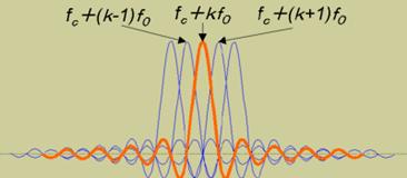
Figure 2.8 Orthogonality of carriers
Figure 2.8 shows a part of the frequency spectrum. Five
subcarriers, also known as pilots, are shown, and it is easy to see that where
the red carrier has a peak, the rest of the carriers have amplitudes equal to
zero. This is a desirable result of the orthogonal nature of the carriers. The
space of 1 kHz between the carriers also helps minimize neighbouring frequency
interference.
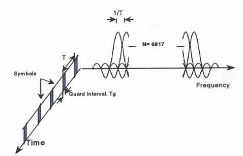
Figure 2.9 The OFDM signal in 8K version
Figure 2.9 shows a time vs. frequency plot of the OFDM signal. N
refers to the number of subcarriers or pilots in the system. The 8K version
showed is used in OFDM for digital video broadcasting terrestrial (DVB-T). The
larger number of carriers is necessary to ensure sufficient bandwidth for the
video signal. Since the bandwidth of the audio signal is not as large as a
video signal, fewer carriers are needed in DAB.
Figure 2.9 also shows what is called a guard period which is
what makes DAB so resistant to multipath reflections. The guard period is
inserted between each sent symbol. In analogue radio, multipath reflection
causes constructive or destructive interference. This is why the reception
quality of analogue radio varies so much in a mobile receiver. The guard time
in DAB increases the probability of having constructive interference from
reflected signals. The guard time can have several lengths. The length is
different for different transmission environments. The choice of guard time
length is a trade off between data rate and signal quality. The guard period
reduces bandwidth and the longer the guard period, the bigger the loss in data
rate. The reflections which arrive after the next guard period are sufficiently
attenuated to not interfere with the new symbol being read. Therefore multipath
reflection is normally not a problem for DAB, even in mobile receivers.
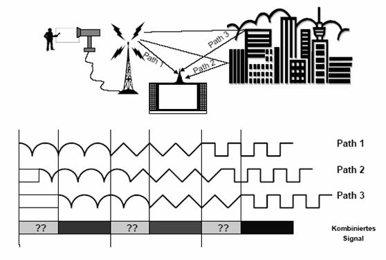
Figure 2.10 The effect of multipath reflection
in an OFDM system
Figure 2.10 shows an example of a broadcasting system with
multipath reflection. The fields with question marks are guard periods. During
this time the end part of the following symbol is sent again to make it more
probable to have positive interference during reception.
This is
provided, of course, that the receiver knows when to sample the received
signal. The figure shows a TV signal sent to a stationary receiver, but the
principle applies equally well to audio signals sent to mobile receivers.
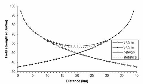
Figure 2.11 Network gain as a function of
distance between two equal transmitters
Figure 2.11 shows a plot of how the signal strength varies with
position between two equally strong, synchronized transmitters. In the absence
of reflection from buildings and the ground, the two transmitter case
corresponds to having one direct signal path, and one reflected signal path.
Because of the guard time and the constructive interference effect shown in Figure 2.10, the received signal is stronger at a given distance
between the two transmitters, than would be the case if the receiver was the
same distance from just one transmitter.
2.3
The
receiver
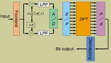
Figure 2.12 COFDM Receiver
Figure 2.12 shows the main parts of a COFDM receiver. The input
is downconverted into two streams, one real and one imaginary part. These are
low pass filtered and analogue-to-digital converted. The cyclic prefix is
removed from the sampled stream. The sampled stream is converted to parallel
and the DFT is calculated. This corresponds to OFDM demodulation. In the
S/P-DFT-P/S block the frequency deinterleaving is also performed. After the
parallel to serial conversion, time deinterleaving and demapping from QPSK is
performed to recapture the original MPEG bitstream.
3
Services DAB provides
3.1 Summary of
Main System Features
The DAB
transmission signal carries a multiplex of several digital services
simultaneously. Its overall bandwidth is 1.536 MHz, providing a useful bit-rate
capacity of approximately 1.5 Mbit/s in a complete "ensemble". Each
service is independently error protected with a coding overhead ranging from
about 25% to 300% (25% to 200% for sound), the amount of which depends on the
requirements of the broadcasters (transmitter coverage, reception quality). The
ensemble contains audio programmes, data related to the audio programme and
optionally other data services [
5]. Usually, the receiver will decode several of these
services in parallel. A specific part of
the multiplex contains information on how the multiplex is actually configured,
so that the receiver can decode the signal correctly. It may also carry
information about the services themselves and the links between different
services.
In
particular, the following principal features have been specified:
Audio Services with a flexible
bit-rate from 8
kbit/s to 384 kbit/s, which allows the multiplex to be configured in such a way
that it provides typically 5 to 6 high-quality stereo audio programmes or up to
20 restricted quality mono programmes.
Data services, each service can be a separately
defined stream or can be divided further by means of a packet structure.
Programme Associated Data (PAD), embedded in the audio bit stream,
for data transmitted together with the audio programme (e.g. lyrics, phone-in
telephone numbers). The amount of PAD is adjustable (min. 667 bit/s), at the
expense of capacity for the coded audio signal within the chosen audio
bit-rate.
Conditional Access (CA), applicable to each individual service
or packet in the case of packet-mode data. Specific subscriber management does
not form part of the DAB System Specification, however, the DAB ensemble
transports the CA information and provides the actual signal scrambling
mechanisms.
Service Information (SI), used for operation and control of
receivers and to provide information for programme selection to the user. SI
also establishes links between different services in the multiplex as well as
links to services in other DAB ensembles and even to FM/AM broadcasts.

Figure
3.1 Generation of the DAB signal
[ 6]
3.2
Details
of the DAB System
Audio Services: Compared to conventional PCM sound
coding, in DAB the bit-rate is reduced sixfold to twelvefold by means of a
digital audio compression technique (see Figure 2-1). It is a low bit-rate
sub-band coding system enhanced by a psychoacoustic model: due to the specific
behaviour of the inner ear, the human auditory system perceives only a small
part of the complex audio spectrum. Only those parts of the spectrum located
above the masking threshold of a given sound contribute to its perception,
whereas any acoustic action occurring at the same time but with less intensity
and thus situated under the masking threshold will not be heard because it is
masked by the main sound event. To
extract the perceptible part of the audio signal the spectrum is split into 32
equally-spaced subbands. In each
sub-band, the signal is quantised in such a way that the quantising noise
matches the masking threshold. This coding system for high-quality audio
signals known as MUSICAM is standardised by ISO/IEC 11172-3 (MPEG 1 Audio Layer
II) and ISO/IEC 13818- 3 (MPEG 2 Audio Layer II). The DAB Specification permits
full use of the flexibility of Layer II except for the fact that only the
standard studio sampling frequency of 48 kHz and the half sampling frequency of
24 kHz are used. Layer II is capable of processing mono, stereo and
dual-channel such as bilingual programmes. Different encoded bit-rate options
are available (8, 16, 24, 32, 40, 48, 56, 64, 80, 96, 112, 128, 144, 160 or 192
kbit/s per monophonic channel). In
stereophonic or dual-channel mode, the encoder produces twice the bit-rate of a
mono channel. The range of possible
options can be utilised flexibly by broadcasters depending on the quality
required and the number of sound programmes to be broadcast. A stereophonic
signal may be conveyed in the stereo mode, or – particularly at lower bit-rates
– in the joint stereo mode. This mode uses the redundancy and interleaving of
the two channels of a stereophonic programme to maximise the overall perceived
audio quality.
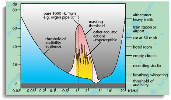
Figure 3.2 Psycoacustic masking
Independent Data Services: In addition to PAD, general data
may be transmitted as a separate service. This may be either in the form of a
continuous stream segmented into 24 ms logical frames with a data rate of n x 8
kbit/s (n x 32 kbit/s for some code rates)
or in packet mode, where individual packet data services may have much
lower capacities and are bundled in a packet sub-multiplex. A third way to
carry Independent Data Services is as a part of the FIC (Fast Information
Channel). Typical examples of Independent Data Services are a Traffic Message
Channel, correction data for Differential GPS, paging and an electronic
newspaper.
Conditional Access: Every service can be fitted with
Conditional Access if desired. The Conditional Access (CA) system includes
three main functions:
scrambling/descrambling, entitlement checking and entitlement
management. The scrambling/descrambling function makes the service
incomprehensible to unauthorised users. Entitlement checking consists of
broadcasting the conditions required to access a service, together with
encrypted secret codes to enable descrambling for authorised receivers. The
entitlement management function distributes entitlements to receivers.
Service Information: The following elements of Service
Information (SI) can be made available to the listener for programme selection
and for operation and control of receivers:
• basic
programme-service label (i.e. the name of a programme service)
•
programme-type label (e.g. news, sports, classical music)
• dynamic
text label (e.g. the programme title, lyrics, names of artistes)
• programme
language
• time and
date, for display or recorder control
• switching
to traffic reports, news flashes or announcements on other services
•
cross-reference to the same service being transmitted in another DAB ensemble
or via AM or FM and to other services
•
transmitter identification information (e.g. for geographical selection of
information)
Essential
items of SI that are used for programme selection are carried in the FIC.
Information that is not required immediately when switching on a receiver, such
as a list of all the day's programmes, may be carried separately as a general
data service (Auxiliary Information Channel).
3.3 DAB-based
Multimedia and Data Services
DAB is not
only a new system for mobile reception of high audio quality and superior
frequency economy, it also opens up opportunities for completely new services.
In the future, there will certainly continue to be programmes similar to
current radio programmes, but these will be supplemented by pictures, texts and
graphics which increase the information value of the programmes. This
combination could be called "Multimedia Radio". Conceivable examples
are traffic and travel information, business information, paging, data to
assist navigation and position determination, remote teaching, electronic
newspapers, games, electronically stored music and various kinds of
moving-picture image services.
Some Key Elements of Multimedia
Broadcast: A
transmission protocol for Multimedia applications and a standard digital
interface are both essential for Multimedia radio. The interface enables extra
devices such as dedicated decoders for Multimedia applications, or computers,
to be connected to a DAB receiver. Both provisions have been put into practice
and will be standardised to encourage the introduction of DAB-based Multimedia
services. Multimedia applications generally rely on files containing relevant
data for the selected service (e.g. text, picture, sound or video transmission)
together with additional information to allow for data presentation and
classification. Each item consisting of a file plus the additional information
is referred to as a "Multimedia Object". The transmission of
Multimedia Objects using all transport mechanisms provided by the DAB system
(Stream mode, Packet mode and PAD) is managed by a protocol called Multimedia
Object Transfer protocol (MOT). The specification of a Receiver Data Interface
(RDI) is an important step to allow DAB receivers and data terminals to be
interconnected in a flexible way. It can convey the entire data multiplex, i.e.
all audio and data channels are accessible by a computer, car navigation
systems or other equipment. The RDI allows high-speed transfer (up to 1.8
Mbit/s) of a wide range of audio and data services in parallel.
Data Management: Due to the steady increase in the
number of potential data providers, such as the media, tourism, transport or
administration, comprehensive data management has been proved necessary. Thus,
e.g. German Data Service Centre (DSC) has been set up forming an interface
between service providers and DAB networks. The DSC will record data of
standardised formats sent in by file transfer, by fax or by telephone, to later
process and introduce this data to a central server and a DAB multiplexer.
3.4
Video
and Information Services
Traffic and Travel Information: Traffic and Travel Information can
be transmitted on DAB in various formats including the TMC (Traffic Message
Channel) protocol developed for the FM Radio Data System (RDS). The following
services can be foreseen:
Traffic messages: Information about traffic problems,
suggestions for route selection, etc. may be transmitted via one of the DAB
data channels. The information can be presented to the motorist by synthesised
speech or on a display in the form of text or maps.
Traffic navigation: Digitised roadmaps are transmitted
and combined with position determination in navigation systems. It will be easy
to find one's way around in large cities, which is of great importance
especially for emergency vehicles, taxis and buses and frequent travellers.
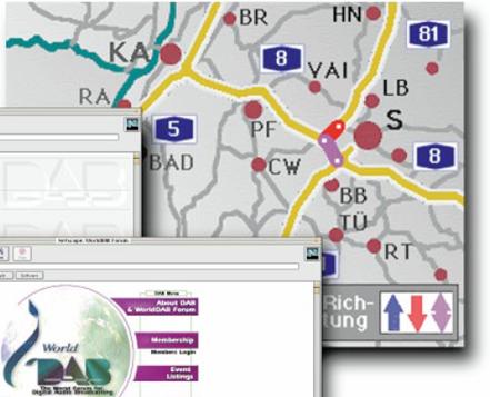
Figure
3.3 Example of a traffic/travel information on a dab receiver
Travel information: Hotel information (vacancies, room
prices, pictures of rooms), local events, location of and space availability in
car parks, petrol stations, timetables, advertisements from local shops and
other information can be transmitted and stored in the receiver and displayed
.
Text Transmission: Textual information is a valuable
supplement to an audio programme and may convey details of the name and
composer of a record playing, information about the current programme including
the phone-in telephone number, an address to send for more information or even
an electronic programme guide. The DAB specification offers two modes for text
transmission:
Dynamic Label: This is similar to the radio text
feature known from the FM-Radio Data System (RDS). It is intended for short
messages to be shown on a simple receiver display of typically up to 16
characters, used to display information, such as radio station names, programme
types. Dynamic Label messages are
limited to 128 characters each.
Interactive Text Transmission System
(ITTS): ITTS is
a more sophisticated text transmission system. It allows for menu-driven
operation, but can also be used to transmit text at the rate a broadcaster
prescribes, for instance in Karaoke-like transmission of lyrics. It can process
several streams of textual information simultaneously, which can be used to
convey the same information in several languages or to transmit a programme schedule
at the same time as giving details of the programme currently on the air. ITTS
supports a number of different display formats, from a 12-character one-line
display to a large colour display.
Electronic Newspaper: A growing number of print media offer
complementary on-line information access services that increasingly integrate
multimedia content. DAB offers novel, innovative electronic media broadcasting
services. They will include all the advantages of online multimedia
information, but also offer the additional benefits of over-the-air
transmission:
• real-time
coverage of large geographic Zones
• immediate
delivery: the newspaper is available as soon as its production has been
completed, anywhere across the country; updates are possible at any time
• a large
readership can be reached at a very low cost per reader
• no
consumption of natural resources (paper) required
The new
system also offers attractive benefits for readers:
• wireless
reception means complete freedom since information is received as easily as a
radio signal. The terminal, for example a PC, may receive the electronic
newspaper or magazine directly, without any action required of the user
• the
newspaper is stored in the computer and available for access on demand
• mobility:
readers can receive a newspaper on a portable computer, even while travelling
• easy
access: subscribers use a "smart card" which enables them to receive
a broadcast newspaper on a computer
• easy
re-use of information (extracting, editing, printing, etc.)
• novel use
of the data, e.g. voice technology
• low
network installation costs Initially, such services will mainly target
professional users.
They will
subsequently be expanded to the consumer market.
Picture Transmission: For still-picture transmission via
DAB, a number of innovative applications can be foreseen. For instance, during
news bulletins photographs could also be transmitted. Weather forecasts and
traffic messages could be illustrated with suitable maps and during music
programmes, the CD cover or a photograph of the performers could be displayed.
In order to transmit pictures in a more efficient way, data compression, e.g.
according to the JPEG standard, could be used. The compressed picture files can
be transmitted separately as Multimedia objects, e.g. as PAD. Pilot projects
have shown that at a data rate of 16 kbit/s a picture can be transmitted within
15 to 60 seconds at an acceptable quality if the JPEG compression factor is
chosen appropriately. The pictures can be displayed consecutively, as in a
slide-show. Therefore, the auxiliary information of the Multimedia objects
specify parameters that enable the receiver to synchronise the display of the
pictures with the audio programme. In addition, files containing texts and
pictures can be transmitted in a HTML (Hypertext- Markup-Language) format as in
Internet/WWW. Thus, Internet services are accessible via DAB.
Differential GPS: GPS, the global positioning system,
is a satellite-based navigation system available all over the world and
provides a positional accuracy of between 300 and 100 metres. By placing an
additional GPS receiver at a precisely known location it is possible to
calculate the error. If this "differential" or error signal is then
also separately fed to the GPS receiver, position accuracy of better than 20
metres becomes possible. Transmission of such data via a DAB data channel in
packet mode is an easy solution for this purpose. By linking mobile GPS
receivers to DAB receivers positional accuracy can be increased significantly.
Figure 3.4 shows an error plot of GPS position measurement for a
fixed receiver with differential information (inside circle) and without
differential information in a first DAB based demonstration of differential
GPS.
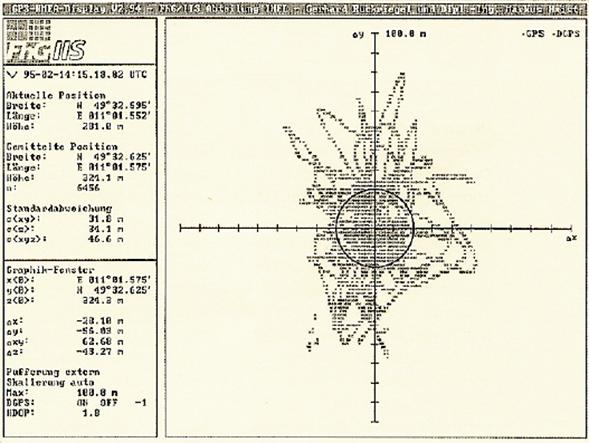
Figure 3.4 Error Plot of GPS
Position Measurement with and withou Differencial Information
TV Transmission to Mobiles: Several public demonstrations have
shown that DAB is a suitable system for the transmission of video and audio
signals – even to mobile receivers. A large market for portable TV-sets and
monitors on public transport is foreseen. It will be possible to receive news
on global and regional events as well as entertainment on the daily way to
work, e.g. by train, bus or on the underground. Video spots on current theatre
and cinema programmes and other local events will provide both information and
advertisement. Demonstrations have shown that the system can be operated at a
rather low video bit-rate of about 1.5 Mbit/s using international standardised
compression algorithms (MPEG1 and MPEG2). Combined video and audio bit-streams
will be embedded in one DAB block leaving additional room for data
applications.
Fax Printout: In situations when reading large
amounts of information on a display is inconvenient – for example when driving
– the possibility of printing graphics or extensive texts can be very
attractive. By using the flexibility of the packet mode (e.g. the variable data
rate) and coupling the DAB receiver with a compact high-resolution printer fax
transmission and reception is also possible. In demonstrators using graphics,
grey scales and G3 faxes, the output was still perfectly acceptable, even on
small-sized paper.
3.5
Satellite DAB
Besides
terrestrial transmission the DAB system is suitable for satellite as well as
for hybrid/mixed terrestrial/ satellite broadcasting, using a simple
omni-directional receiving antenna. Satellites will receive the data generated
by uplink stations, amplify this data and send it back through special spot
beams not only to fixed, but also to mobile and portable receivers.
Complementary terrestrial transmitters may be necessary, e.g. in big cities
with high-rise buildings. In contrast to conventional TV-satellites, where
radio programmes can only be picked up with the help of special receivers, and
dishes have to be installed, the DAB satellite system will have the same
modulation/ coding system parameters as the terrestrial system. Thus, the same
receiver and antenna can be used both for terrestrial and satellite DAB. Field
tests on Satellite DAB have been conducted recently – one in
Satellite
simulations with helicopters were also carried out. To provide high-quality,
mobile reception, elevation angles of 60 to 70 degrees were found to be
necessary. With Satellite DAB it will be possible to cover areas much larger
than those covered by terrestrial broadcast stations. A geostationary (GEO)
satellite system could cover low-latitude areas, such as most parts of Africa,
Central and
4
The
status of DAB across Europe
4.1
Coverage
today
When in
1998 the first DAB receiver reached the European market many countries all over
But even in
2004 the level of terrestrial digital radio coverage differs significantly from
country to country.
In some of
them digital radio services already cover a large proportion of the population.
For instant Belgium with 98 per cent coverage, the UK with 85 per cent
coverage, Germany with 78 per cent coverage and Portugal with 75 per cent
coverage [ 8]. The multiplex operators in these countries are
generally required to meet a minimum coverage level as a condition of their
licence.
For
example, the
A number of
other markets have no such regulations, such as
To obtain a
better idea of the coverage in certain European countries more detailed
information about is given about
4.2
Portugal
Figure 4.1 DAB Coverage in Portugal [ 7]
The public
broadcaster RDP started DAB pilot broadcasts in January 1998. During Expo98, in
There are
39 transmitters in use, 27 in the mainland, 7 in Azores and 5 in
It’s
expected that the Digital Radio will substitute MW and FM until the end of
2010.
|
First Radio
Stations |
Kind of
program |
Service
type |
launched |
|
Antena 1 |
Nationwide
information and entertainment |
public |
22/05/98 |
|
Antena 2 |
Classical
Music and Culture |
public |
22/05/98 |
|
Antena 3 |
Youth
Music, Music News |
public |
22/05/98 |
4.3 Austria
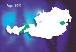
Figure 4.2 DAB Coverage in Austria [ 7]
There is
currently one multiplex operating with three transmitters in
|
First Radio Stations in |
Kind of
program |
Service
type |
launched |
|
Ö1 |
Classical
Music and Culture |
public |
01/01/99 |
|
Ö2 (Radio
Wien) |
Local
news and folk music |
public |
01/01/99 |
|
Ö3 |
Pop
music, Nationwide information |
public |
01/01/99 |
|
FM4 |
Youth
Music, Music News |
public |
01/01/99 |
|
First Radio Stations in |
Kind of
program |
Service
type |
launched |
|
Ö1 |
Classical
Music and Culture |
public |
01/09/00 |
|
Ö2 (Radio
|
Local
news and folk music |
public |
01/09/00 |
|
Ö3 |
Pop music,
Nationwide information |
public |
01/09/00 |
|
FM4 |
Youth
Music, Music News |
public |
22/05/98 |
4.4 Germany
Figure 4.3 DAB Coverage in Germany [ 7]
In
In April
1999, the eastern German state of Saxony-Anhalt was the first to launch Digital
Radio services. More than 95% of the area, and virtually all of the 2.7 million
inhabitants were covered from the start.
In May
1999,
Meanwhile,
Baden
In
As well as a
DAB commission within ZVEI, the German consumer electronics manufacturers’
association, which is trying to improve receiver penetration through
co-operation with broadcasters and the automobile industry, the Initiative
Marketing Digital Radio (IMDR) was launched on 9th May 2001. Members of the
initiative are all network operators in
|
First Radio Stations |
Kind of
program |
Service
type |
launched |
|
Radio |
Local
Information |
public |
26/08/95 |
|
Frankfurt Business Radio |
Business
news about the stock market |
public |
01/04/97 |
|
|
|
|
|
|
|
Ensemble in Saarland |
|
|
|
SR 1 Europawelle |
Nationwide
information and culture |
Public |
17/12/96 |
|
SR 2 KulturRadio |
regional
content plus classical music |
Public |
17/12/96 |
|
Radio Salü |
Local
radio with the french touch |
Commercial |
17/12/96 |
|
|
|
|
|
|
|
Ensemble in
North-Rhine |
|
|
|
Power Radio |
Youth music |
commercial |
30/01/97 |
|
WDR 1 Live |
Rock & Pop music |
public |
30/01/97 |
|
WDR 2 Klassik |
regional
content plus classical music |
public |
30/01/97 |
|
WDR 3 |
Classical music |
public |
30/01/97 |
|
Deutschlandfunk |
Nationwide
information and culture |
public |
30/01/97 |
|
DeutschlandRadio Berlin |
Nationwide
information and culture |
public |
30/01/97 |
|
WDR-InfoKanal |
Federal State Information |
public |
30/01/97 |
|
WDR Verkehrskanal |
Traffic announcement |
public |
30/01/97 |
All other
provinces of the country launched their first DAB stations in the beginning of
1999.
4.5 Italy
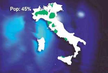
Figure 4.4 DAB Coverage in Italy[ 7]
Five
national public services are simulcast on the public multiplex, reaching
approximately 20% of the Italian population. Coverage on Ch 12, part of the
public service charter, has been significantly reduced in order to allow the
deployment of DVB-T along with the mandate of the new broadcasting law still to
be approved by the Parliament. The commercial multiplex, which is operated by
Club DAB Italia, and simulcasts six commercial and two non-profit FM services,
is now on hold while it awaits a stable regulatory framework and is planning to
start regular service. The private consortium EuroDAB has extended its trial
coverage in some of the main populated areas reaching about 50% of the
population. Their transmitters now provide coverage in Roma,
Among
private operators Club DAB Italia has modified its membership and now includes
a total of 9 stations licensed for national coverage. EuroDAB is now composed
of 3 national and 2 local licensed operators. A new consortium has been set-up
composed of one national station and a set of regional stations but has not
started its trials yet.
Coverage
layers in the
Further
development of Digital Radio poses the key issue of switch over from trials to
regular service. Main trial coverage of the multiplexes is still limited to
patches in the North-Western part of the country along the route from
In
mid-2002, the Italian Communication Authority released a frequency assignment
plan for DAB that anticipated:
in band
VHF-III, two layers with national coverage (SFN) to be used by national
services and one regional coverage (2-SFN) to be used for services that need a
differentiation that approximately match the Italian administrative regions.
in band
UHF-L, four layers with local coverage (4-SFN) designed upon the needs of local
operators.
The plan is
based on allowing a minimum of seven services for each multiplex, but it does
not take into account the situation at the borders nor the international
frequency co-ordination aspects. In VHF-III it is based on Ch 12 only. Its
publication has encouraged a new interest in DAB Digital Radio from local
private broadcasters. However, the radio sector is now on hold awaiting
clarification on the spectrum management issues and the new broadcasting law,
as both aspects are linked to investment opportunities. Regarding spectrum the
main drawback is linked to the pressure from public service DVB-T plans upon
VHF band III that allows marginal resources to Digital Radio.
National
public and commercial stations share the majority of the audience, but local
stations remain important to the communities they serve. As digital
broadcasting legislation is proposed, care will need to be taken for Digital
Radio to maintain the balance currently enjoyed by analogue stations.
|
First Radio Stations |
Kind of
program |
Service
type |
launched |
|
RAI Radio 1 |
News |
public |
01/05/98 |
|
RAI Radio 2 |
Music and Entertainment |
public |
01/05/98 |
|
RAI Radio 3 |
Classical Music & Culture |
public |
01/05/98 |
4.6 Norway
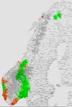
Figure 4.5 DAB Coverage from the 26th of february[ 7]
Figure 4.6 from the 19th of november
The
national network went into regular service on 1st February 1999 with public and
commercial services. Public broadcaster NRK has been assigned 4/6 of the
capacity. The remaining capacity has been divided between the commercial FM
station P4 Radio Hele Norge and Kanal 5 (Radio 2 Digital) who received their
licence in August 1999.
The network
currently covers about 70% of the population with 34 DAB transmitters. The
coverage is being planned with careful attention to continuous coverage on
important main roads in the area. You can drive South/North from Porsgund and
Steinkjer (ca 900 km) whilst listening to DAB. The route covered follows the
two main roads between
Norkring
plans to extend the coverage to 95% within a few years.
The second
national coverage is adapted to serve NRK’s regional programs. The first phase
of this network, covering the region around Oslofjord, is in operation. This is
the area where most of the people live and with 21 transmitters, almost 30% of
the population is covered.
The service
providers are now focusing further on new audio and data services, as well as
video over DAB. Different DLS-text and audio services were launched during
autumn 2001. The service providers are prepared to deliver more advanced data
services as soon as receivers with this kind of functionality are available.
Once receivers are introduced on the market, new services will also be
launched.
Currently,
NRK P2, P3, and P4 Radio simulcast their existing analogue services.
Additionally, there are some exclusive services: NRK Alltid Nyheter (24 hour
news), NRK Alltid Klassisk (24 hours classical music) and NRK Stortingskanalen
(parliamentary network), NRK Sami Radio (ethnic) and met.OSLOFJORD (weather
service for the Oslofjord). Radio 2 Digital went air with their new programme
in October 2001.
All the
service and network providers have a formalised co-operation covering strategic
and marketing questions. A co-ordinated market plan has been prepared between
the parties. This
work is
co-ordinated with the activities in the WorldDAB Technical and Marketing
Committees.
|
First Radio Stations |
Kind of
program |
Service
type |
launched |
|
NRK „ensemble“ |
4 Stations
(News, different music….) |
public |
01/02/99 |
|
P4 Radio Hele Norge |
PAD:
programme title, name of DJs, telephone numbers, name of artist, song info;
news headlines and traffic messages interrupt the above when there is news. |
commercial |
01/02/99 |
5
Other
Digital Radio Techniques
5.1
DRM - Digital Radio Mondiale
History of
DRM:
DRM
emerged from an informal meeting in Paris, in September 1996,where some of the
large international broadcasters and broadcasting equipment manufacturers mentioned
that the days of broadcasting in the AM bands below 30 MHz were limited.
The
meeting agreed that a group needed to be established whose task would be to
define the structure for a formal organisation to be called Digital Radio
Mondiale (DRM).
Its main
objectives would be:
-
to
formulate a digital AM system design, which could serve as a single, tested,
non-proprietary, evolutionary world standard, which would be market driven and
consumer oriented
-
to
facilitate the spread of AM digital technology around the world
On April
4, 1997, in Las Vegas, Nevada, U.S., the first formal meeting of Digital Radio
Mondiale took place during the NAB ’97. Over 40 delegates from all sectors of
the industry, and most regions of the world, attended the meeting.
In August
1997, the Third Organisational meeting of DRM was held at IFA97 in Berlin,
Germany. With a growing interest, some 48 representatives of the broadcasting
industry met.
On March
5, 1998, twenty of the world's most important broadcast-related organisations
signed the Digital AM Memorandum of Understanding in Guangzhou, China, thus
putting DRM on a formal footing, as a first step to the official inauguration.
On
September 10, 1998 in Amsterdam, the Netherlands, the Consortium Agreement
replaced the Memorandum of Understanding.
A final
milestone was the approval of DRM by the European Telecommunications
Standardisation Institute (ETSI) in September 2001.
The first
Radio programme started on the 16th June 2003.
An
up-to-date programme guide can be seen at: http://www.rnw.nl/realradio/html/drm_schedule.html
About DRM:
Digital Radio Mondiale is a
narrowband digital radio system designed for use in the low frequency (LF) medium
frequency (MF) and high frequency (HF) terrestrial broadcasting bands below 30
MHz. DRM was originally designed as a green fields solution in that it requires
a clear frequency to operate effectively. It was designed to augment existing
services by operating with the existing channel spacing employed for amplitude
modulated (AM) broadcasting and for HF broadcasting worldwide. It can carry
audio and/or data with the flexibility to trade-off between audio quality, data
capacity and signal robustness. More recently, work has been undertaken to
develop a version of the DRM system designed to facilitate conversion of
analogue services by permitting simulcasting in analogue and digital modes.
Under this system, it is proposed that the analogue and DRM transmissions would
occupy the same bandwidth as an ordinary AM-MF service. This variant of DRM is
still under development and it is not possible to evaluate its claims.
DRM operates on lower bit rates and
therefore offers lower audio quality compared to most other digital radio
systems. Options for the introduction of DRM in MF spectrum include
identification of remaining available channels or the freeing up of some
existing MF-AM channels for DRM.
Implementation of DRM in the HF Band
is also problematic. HF propagation relies on sky wave propagation through the
ionosphere [ 9], the state of which changes
throughout the day. HF broadcasters are often required to transmit the same
signal at different frequencies, or to regularly change transmitting frequency,
in order to increase the probability of reception in the intended target area.
Use of the HF broadcasting bands is also subject to international coordination
and recent ITU studies have shown these bands are already heavily congested.

Figure
5.1 Sky wave reflection [ 9]
Audio Compression Standard:
MPEG-4 takes a different approach to
MPEG-1 and MPEG-2 and addresses speech and video synthesis, fractal geometry, computer
visualisation, and an artificial intelligence approach to reconstructing
images. MPEG-4 uses a tool-based approach to create audio at very low data
rates (2 - 64 kbit/s). The tools include: text-to-speech, music synthesis,
speech coders, surround sound, audio coding and the ability to mix and change
the received audio.
MPEG-4 AAC is the MPEG-4 audio
coding tool. It incorporates MPEG-2 AAC with additional tools increasing the
effectiveness of MPEG-2 AAC at lower data rates, and adding scalability and
error resilience characteristics.
A German Company, Coding
Technologies GmBH, increased the efficiency of MPEG-4 AAC using their Spectral
Band Replication technology to develop aacPlus (also known as CTaacPlus). This
technology was subsequently incorporated into the MPEG standards system as
MPEG-4 High Efficiency AAC or MPEG-4 HE AAC.
Relation to DAB:
As DRM is a transmission standard
for frequencies lower as 30 MHz, it won’t be an opponent to DAB. Their relation
will be similar to the one AM has to FM nowadays. Furthermore the WorldDAB
Forum, the European based organisation charged with promoting Eureka take up
around the world, and the DRM Consortium have recently agreed to ‘collaborate
on the development of their systems’ and to ‘foster conditions that are
favourable for both digital systems’.
Main
differences to DAB:
-
The
aim of DRM is to produce a broadcasting standard for frequencies below 30
megahertz. It shall substitute the 3 AM waves (SW, MW and LW).
-
It
uses 16/64 QAM (see 2.1)
-
18khz
to 1536khz Bandwidth
-
Different
modes for different use (Figure
5.2)
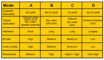
Figure 5.2 Different transmission modes
Why is Digital Radio needed below 30
MHz ?
There is
a global trend towards the adoption of digital technology in radio and
communications, especially for distribution and transmission. Digitalisation
offers many substantial advantages to national / international broadcasters and
infocasters.
We are
seeing the introduction of high quality delivery system in homes. FM sound
broadcasting is gradually moving to a DAB standard.
But
coverage on FM 88-108 MHz (VHF) is limited. For many national and international
broadcasters, the advantages of a complementary digital broadcast system BELOW
30 MHz are becoming clear. However, the limited fidelity of existing AM
services is causing listeners to search for other alternatives.
Implementation
of digital radio in today's AM bands (i.e. long, medium and shortwave) will
enable operators to provide services which will be successful with both
existing and future high-quality services operating on other parts of the dial.
Digital
broadcasting on short-, medium-, or longwave (AM) has many advantages when
compared to the conventional analogue system we use now.
Benefits of Digital AM for Listeners
-
FM-like
sound quality with the AM reach;
-
Improved
reception quality;
-
Flexible
use of radio, whenever and wherever you want it;
-
No
change to existing listening habits:
-
same
frequencies,
-
same
listening conditions (fixed, portable and mobile radio),
-
same
listening environment (indoors, in cities, in dense forests..)
-
Low
cost receiver, low energy consumption;
-
Easy
tuning: with selection by frequency, station name or programme type;
-
More
diverse programme content, using the full capabilities of new digital features;
-
Wide
receiver range with more and better features;
-
Radios
that will give you programmes with associated text information, station name,
record title, singer’s name...
Benefits of Digital AM for Receiver,
Transmitter and Semiconductor Manufacturers
-
Bringing
longevity to older AM technologies;
-
Opportunity
to identify possibilities for new areas of interest;
-
Increase
the market potential for transmitting and receiver systems;
-
Optimise
return on investment for dual technology components for low data rate systems
applied to narrow-band transmission channels;
-
Opportunity
to effectively influence the cost-effective design cost of future AM radio
systems;
-
Possibility
to replace 2.5 billion receivers with digital AM receivers;
-
Through
DRM active participation in AM digital development.
Benefits of Digital AM for Broadcaster
-
Continued
use of existing transmission systems
-
Continued
(and more efficient) use of existing frequency planning;
-
Independent
editorial control;
-
Control
of coverage area;
-
Rapid
and short-term flexibility when required;
-
Opportunities
for added-value services with data, text and other services;
-
Better
audio quality for listeners, wherever they live;
-
Increased
audience interest, resulting from audio quality improvement and additional
services;
-
Increased
advertising interest, resulting from increased audience interest;
-
As part of DRM, active participation in the development of
"digital AM" radio broadcasting and an opportunity to contribute to
the implementation of "digital AM" radio.
5.2
DVB-T
The DVB project has developed a number
of related digital broadcasting systems for cable, satellite and terrestrial
delivery of television services. These are known as DVB-C, DVB-S and DVB-T
respectively. While all these systems were primarily designed for television
broadcasting they can and do provide radio (audio-only) programs.
DVB-T is sufficiently flexible to
allow it to be optimised for delivery to portable and mobile receivers.
Consumer grade mobile DVB-T receivers are likely to be produced with the aim of
providing mobile television and multimedia services.
DVB-T is a proven technology for
digital television, and has been implemented in many countries. It is capable
of operating over a wide range of frequencies providing broad scope for the
identification of suitable spectrum.
Challenges with implementing DVB-T
for digital radio centre on the need for good mobile and portable reception and
its large bandwidth usage. DVB-T is not optimised for mobile reception and no
mobile or portable hand held receivers are available. The high data rates and
wide bandwidth needed to operate the system not only increases power
consumption but also makes the design of battery-powered devices difficult.
That’s why a more power efficient version of DVB-T, called DVB-H (H for
handheld), is being developed. It will work with about 35% of the battery
consumption DVB-T needs. DAB only needs 5%-20% of it.
The large bandwidth use required for
DVB-T means that many services must be multiplexed together for efficient use
of the spectrum and there is a risk that such multiplexes may not be fully
utilised thereby leading to inefficient spectrum use.
However, experience here and
overseas suggests that platforms designed primarily for digital television are
likely increasingly to carry audio-only entertainment and information as well,
whether on a subscription or free-to-air basis.
5.3
IBOC
IBOC (In
Band On Channel) is the American attempt to enter the area of digital radio. It
is a narrowband system which is designed to allow for the implementation of
digital radio in two phases. The first is a Hybrid phase, which supplements an
existing AM or FM analogue radio signal with a digital signal carried alongside
the transmission of the analogue signal. The second is an All-Digital phase in
which the analogue signal is removed and the digital signal reconfigured to
optimise system ruggedness and maximise coverage areas. In the Hybrid phase,
the analogue and digital services need to be identical as the IBOC receiver is
designed to use the analogue service as a “fallback” signal when the digital
signal drops out at the edge of coverage. IBOC has two system variants, IBOC-AM
for use in the MF-AM band and IBOC-FM for use in the VHF-FM band.
The IBOC
system design enables broadcasters to maximise the use of existing
infrastructure thereby minimising upgrade costs and, from a consumer
perspective, allowing a progressive migration from analogue to digital. Its
receiver design avoids abrupt reception failures common in digital systems at
the edge of the coverage area.
IBOC’s
system design, however, is relatively immature and is still being standardised.
Its operational range and quality also needs to be further tested before it can
be properly considered in terms of its suitability for the countries.
The audio
quality of IBOC (in particular the AM variant) is currently under review by
system developers. Compared to other digital radio systems IBOC-AM would offer
much lower quality audio; while the greater data capacity of IBOC-FM
accommodates a stereo digital audio service in addition to the existing stereo
analogue service.
5.4 ISDB-TSB
Integrated Services Digital Broadcasting-for Terrestrial Sound
Broadcasting:
It was developed in
ISDB- TSB is designed for low power
consumption of receivers to allow portable battery operated devices to be
manufactured. While the potential capabilities of ISDB- TSB have been described
it has not yet reached the stage of an operational deployment. There are
currently no ISDB-TSB transmissions or consumer receivers although trial
services may commence in 2003.
5.5
Digital
Radios over Satellite
Besides S-DAB
(see 3.5) and DVB-S exist some other satellite radio standards
that should be mentioned here:
US based Satellite Digital Audio Radio Services (SDARS):
Two similar satellite delivered
subscription radio services providing approximately 100 audio channels each
have commenced operation in the
Worldspace Satellite:
Current Worldspace services aim to
provide radio and data services to underserved regions through portable battery
operated devices in less developed countries including areas where
infrastructure such as mains power may not be available.
Worldspace
digital radio technologies consist of two satellite transmission systems for
operation in L-band at approximately 1.5 GHz. The first of these two systems is
operational and provides coverage to Asia, Africa, the Middle East and
potentially parts of Europe through two geostationary orbiting satellites to
relatively simple portable radio receivers. The two operational satellites are
named ‘Afristar’ and ‘Asiastar’. A third satellite was intended to cover
Central and
5.6
Available
frequency bands
Digital
radio services may potentially be implemented in one or more spectrum bands
with each band having different coverage properties and existing usage (e.g.
navigation aids, broadcasting services, point-to-point radio communications,
land mobile, radar, etc).
The
coverage of a digital radio service depends not only on its system
characteristics and radiated power, but also on the spectrum band used and, in
particular on the propagation or way the signal travels from the transmitter to
the receiver. In different spectrum bands a digital radio emission may
propagate by “bouncing” off layers of the atmosphere; follow the curvature of
the earth; or travel directly from one point to another. The emission may pass
through or around obstacles in one band that would completely block the
emission in another band. In some bands coverage may also vary on an hourly,
daily, seasonal or multi-year basis as radiation from the sun affects the
height and density of the atmospheric layers. This is mostly apparent at lower
frequencies which are refracted by the atmosphere while higher frequencies tend
to pass through, or are attenuated by, the atmosphere.
Other
factors that change with the spectrum band used are the amount of information
or data that can be transmitted; the size and nature of the transmission and
reception antennas and the effect of interference from the sun, system noise
and man-made source such as power lines and electrical motors. Satellite
systems are feasible in frequency bands in the vicinity of 1 - 3 GHz. Below 1
GHz, too much power must be transmitted to overcome man-made noise and the size
of the antennas on the satellite are too large for practical use. Above 3 GHz,
the gain of a practical omni-directional receive antenna is too low to provide
a reasonable service without a significant increase in satellite transmit
power.
The
International Telecommunication Union (ITU) manages the international
co-ordination of radio communication services. The ITU has divided the world
into three regions. Region 1 covers Europe (including
At the
WARC-92 (World Administrative Radio Conference) the ITU defined the following
frequency bands as appropriate and access able in short term for digital radio:
VHF Bands
I, II and III,
UHF Bands
IV and V and the
1.5 GHz,
2.3 GHz and 2.6 GHz bands
Low Frequency (LF)
The LF band
is 30 - 300 kHz. In Europe (ITU Region 1) the band 148.5 - 283.5 kHz is
allocated to the broadcasting service, but there is no corresponding allocation
for the broadcasting service in ITU Region 3 (which includes
Medium Frequency (MF)
The MF band
is 300 - 3000 kHz. Parts of the MF band, including 526.5 - 1606.5 kHz in ITU
Regions 1 and 3, and 525 - 1705 kHz in ITU Region 2 are used for AM
broadcasting services. The MF wave transmission occurs by means of ground wave
and sky wave. Mainly the ground wave propagation is used for coverage. Ground
wave propagation is slightly less effective in the MF band in comparison to the
LF band. Sky wave transmission is generally not intentional and may cause
interference to distant services. This sky wave transmission mode necessitates
international coordination of broadcasting services in the MF band. These
services are also referred to as “medium-wave” services (MW).
High Frequency (HF)
The HF band
is 3 - 30 MHz. A number of bands have been allocated to the broadcasting
service within the HF band. These allocations include frequency bands from 2.3
- 27 MHz. The HF broadcasting allocations are generally used for national or
international broadcasting on a worldwide basis. These services are also
referred to as “short-wave” services (SW).
Under
favourable propagation conditions HF transmissions can cover very large
distances, using sky wave propagation as the intended transmission mode. As
reception depends on the frequency of the transmission and the state of the
ionosphere (part of the atmosphere), broadcasters operating on HF are often
required to transmit the same signal at different frequencies, or to regularly
change transmitting frequency, in order to increase the probability of
reception in the intended target.
Very High Frequency (VHF)
The VHF
Band is 30 – 300 MHz. Within the VHF Band there are three bands used for
broadcasting as outlined below.
Very High Frequency (VHF) Band I
VHF Band I
includes frequencies from 45 - 70 MHz and has, in part, been used to provide
channel 0, 1 and 2 analogue television services (amongst other non-broadcasting
uses). VHF Band I transmissions generally follow the curvature of the earth but
may also bounce off the atmosphere, particularly in the summer months. Services
in VHF Band I are also particularly susceptible to interference from man-made
noise.
Very High Frequency (VHF) Band II
VHF Band II
covers 87.5 - 108 MHz and is generally used for FM broadcasting. VHF Band II
transmissions have lower anomalous seasonal propagation problems than VHF Band
I but are still susceptible to interference from man-made noise.
Very High Frequency (VHF) Band III
VHF Band
III covers 174 - 230 MHz and is generally used for television broadcasting. The
spectrum from 230 - 240 MHz is used for radio communication services,
particularly by defence, but has been identified as being possibly suitable for
digital radio services, particularly in
Ultra High Frequency (UHF) Band IV and V
The UHF
Band is 300 – 3000 MHz. Within the UHF Band there are two sub-bands that are
generally used for terrestrial analogue broadcasting. UHF Band IV covers 470 -
582 MHz and UHF Band V covers 582 - 820 MHz. They are generally used for
television broadcasting.
UHF Band IV
and V transmissions travel more or less in straight lines with greater curving
or diffraction evident at the lower frequencies. While the UHF bands are not
generally affected by man-made noise and anomalous propagation to the same
extent as VHF transmissions, they do not cover as wide an area as they tend to
be attenuated by local terrain obstructions such as buildings, hills and trees.
L-Band
The L-Band
covers 1 – 2 GHz and is part of the UHF Band. The sub-band 1452 - 1492 MHz has
been identified by the ITU as suitable spectrum for terrestrial and satellite
delivered digital radio services. The band was allocated to the broadcasting
service and the broadcasting satellite service (sound) in all three ITU regions
at the ITU World Radio Conference in 1992 (with a few countries opting out –
including the
S-Band
The S-Band
covers 2 – 4 GHz and overlaps the UHF and SHF (3 - 30 GHz) Bands. Two sub-bands
2310 - 2360 MHz and 2535 - 2655 MHz have been identified by the ITU as suitable
spectrum for satellite delivered digital radio services for certain countries.
The lower band is available in the
5.7
Overview
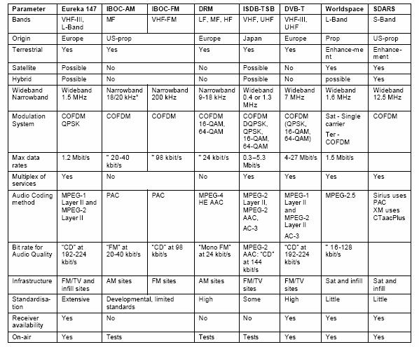
Table 5.1 Table of different digital Radiosystems
6
Epilogue
6.1
Conclusion
There is a
drive from the governing authorities of many countries today towards
digitalising radio broadcast. There are several reasons for this, including a wish
to make room for new channels, a wish for improved reception quality and a wish
for easier frequency planning. DAB is already in use in many countries all over
the world. There are concrete plans in several countries to have nation wide
DAB coverage within just a few years. Parallel to this are plans to stop
analogue broadcasting just a few years after full DAB coverage has been
achieved. The time scope for the transition from analogue to digital
transmission is 10-15 years in countries like for instance
From a
technical point of view DAB is a well defined standard, with much flexibility
to counter various topographies. This will ensure good quality reception even
in areas where analogue radio has problems today. The modulation technique
behind DAB, COFDM, is used in every new standard of digital transmission that
is coming out.
As the
development of DAB took over 20 years, the audio encoding it uses (MPEQ1 Audio
Layer II) is not up-to-date anymore. For a better “bandwidth use to quality”
ratio audio codecs like AAC (used in ISDB-TSB) and HE AAC (used in DRM) are
recommended for digital transmission.
Also it
should be mentioned that more recent standards (DVB-H) are able to use 16-QAM
or 64-QAM for mobile reception, because of a better FEC (forward error
correction).
6.2
Abbreviations
For the
purposes of the present document, the following abbreviations apply:
AM
Amplitude Modulation
CA
Conditional Access
CI Contents
Indicator
CIF Common
Interleaved Frame
CRC Cyclic
Redundancy Check
D-QPSK
Differential QPSK
DAB Digital
Audio Broadcasting
EBU
European Broadcasting
ETS
European Telecommunication Standard
FFT Fast
Fourier Transform
FM
Frequency Modulation
IEC
International Electrotechnical Commission
ISO International
Organization for Standardization
MPEG Moving
Pictures Expert Group
OFDM
Orthogonal Frequency Division Multiplex
PAD
Programme Associated Data
PCM Pulse
Coded Modulation
QPSK
Quadrature Phase Shift Keying
RDS Radio
Data System
SFN Single
Frequency Network
SI Service
Information
UHF Ultra
High Frequency
UPC
Universal Product Code
UTC
Co-ordinated Universal Time
VHF Very
High Frequency
6.3
References
The
following documents contain provisions which, through reference in this text,
constitute provisions of the present
[ 1] http://www.digitalradiotech.co.uk/cofdm.htm
[ 2] COFDM: new communication possibilities (ProTelevision Technologies)
[ 3] Planning of Single Frequency Networks (ITU/EBU WS on Digital Broadcasting, Sofia 8-10 June 2004)
[ 4] “Heterogene
Systeme” (Lecture notes by Eckhardt Holz)
[ 5] EU Information brochure about DAB - Eureka 147, DLR
[ 6] http://www.worlddab.org/images/figure_1.jpg
[ 7] Country Status Information, http://www.worlddab.org/cstatus.aspx
[ 8] Digital Radio Study Group Information Paper - Australian
Broadcasting Authority September 2003
[ 9] 6th Sixth Framework Programme by the QoSAM
(Quality of Services in digital AM)